Build a small audio amplifier using common transistors. Gives you 300mW to an 8 ohm speaker. Single-sided PCB design available.
Here is the schematic of a small audio amplifier that will provide up to 300mW to an 8 ohm load and can be used in low power devices like battery powered radios. This circuit is an alternative to the LM386 IC. Due to the simplicity of the schematic, the circuit can be built also on breadboard, for those of you who want to experiment and learn how an amplifier works.
The design is straightforward. A common small signal NPN transistor (like BC547, 2N2222, 2N3904, S8050) drives a balanced power amplifier made of similar transistors. The output transistor pairs can be BC327 with BC337 or S8050 with S8550. They must handle peak currents of 300-400mA (this is why BC547/BC557 or 2N3904/2N3906 should not be used here). The amplifier can be powered from a 9V battery or from a 12V power source. The circuit draws a current of about 170mA. Quiescent current is less than 10mA.
 |
| Audio amplifier build on breadboard |
I built the amplifier on a breadboard and tested the output stage with BC327/BC337 and S8050/S8550 pairs (the latter are seen in the above picture). If the input signal is too high, the output transistors will get hot and smoke may come out of them. This is because the quiescent current is proportional to temperature. To avoid this, make sure you keep the input signal less than 1.5 Vp-p. Here is the breadboard design in Fritzing (with BC327/BC337 transistors, which have different pinout than S8050/S8550):
 |
| Audio amplifier breadboard |
Next is the schematic and PCB for this circuit. If you will look carefully, you may notice that on the breadboard and in Fritzing I used different values for some of the parts. This is because I did some tests and if you want to build the circuit, follow part values from the below schematic:
 |
| Mini audio amplifier schematic (both channels) |
The schematic is for both channels. Resistors R4 and R8 and diodes D1, D2 and D3, D4 set quiescent current. R4 and R8 may be lowered down to 1.8-2 kiloohms (as I did on the breadboard) if powering the circuit from a 9V battery. Amplification is determined by R1 and R3 (R5 and R7). The current values are suitable for line out audio level of 1 to 1.4Vp-p. If a lower level signal is fed to the circuit, R1/R3 should have smaller values too. You should not alter R3/R2 (R7/R6) ratio because this sets the DC operating point of the amplifier.
 |
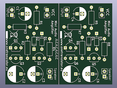
| Mini audio amplifier PCB |
The single-sided PCB design is for both channels yet it can be cut in half. Output transistors footprint is for S8050/S8550. If you decide to use BC327/BC337 rotate them 180 degrees. I built this on the PCB and it works way better than on breadboard. Although the output power is not much, the sound is good.
 |
| Built prototype of mini audio amplifier |
Resources: KiCad project with Gerber files (archive is ready to send to PCB manufacturer).


C1 and C4 polarity should be reversed. In DC the right side will be at +0,6 V and the left at 0 V.
ReplyDelete