Autoranging capacitance meter with LCD display

 Posted by:   Posted on:    4 comments

A capacitance meter is an useful test gear. And since my multimeter is too crappy to get a constant reading, I decided to make my own meter, especially for large capacitances. With an Arduino development board, a display and some resistors, the capacitance meter was almost built. It needed proper software to charge and discharge the capacitor, then measure time constant and compute capacitance. A capacitor's value can be determined by placing it either into an L-C oscillator and measuring frequency, either in R-C circuit and measuring time constant. While the first method requires some additional parts and it is difficult in terms of software, it is able to measure small capacitances and also inductors (by using a known value capacitor and calculating the inductor).

This project uses the second method, with RC circuit. If a voltage is applied to a series resistor - capacitor circuit, the latter tends to reach supply voltage at its pins (it charges). The charging needs a time dependant on series resistor and capacitor value. It should be noted that the capacitor draws current as it modifies the voltage across its pins. The following circuit performs both charging and discharging of capacitors. However, measurements are performed only during charging. The discharge function allows Arduino to make multiple measurements of the same capacitor without taking it out of this circuit.

Autoranging capacitance meter with LCD display

Capacitance meter wired on the breadboard

Alarm clock with DS1302 RTC

 Posted by:   Posted on:    18 comments

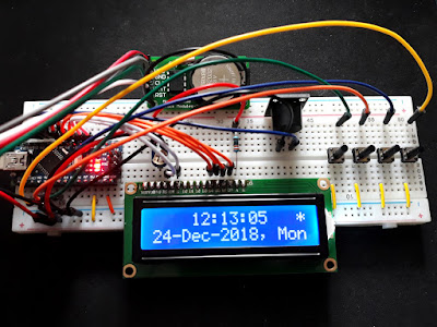
DS1302 is a timekeeping chip with battery backup and general purpose RAM. It has been replaced by newer variants like DS1307 or DS3231 which have improved accuracy. The newer ones have I2C interface, but DS1302 does not. It communicates with the host using a serial protocol that resembles SPI. Since I had a module with this chip, I decided to build and test an alarm clock. I added an Arduino, the alphanumeric LCD, an active buzzer and some buttons.

There are some great advantages when using an RTC (real time clock) module in your project. You don't have to do timekeeping in your code (if you read my previous post, you can see it's not quite easy) and, very important, time keeping is performed from backup battery when your development board is not powered. This means you don't have to set date everytime you plug in the Arduino. The advantage is obvious for projects that depend on accurate time to operate correctly.

Arduino alarm clock with DS1302 RTC module

Drive the multiplexed 4 digit 7-segment display

 Posted by:   Posted on:    No comments

Seven segment displays are widely used in clocks, meters and other devices that need to display numerical information. The elements of the display, which are usually made from LEDs, are lit in different combinations to represent Arabic numerals. They have a limited ability to display some characters because there are only 7 elements that compose the shape of the displayed figure. Seven segment displays are very easy to find and are the cheapest display type.

In the previous post I talked about the electrical connections of such displays and how they should be interfaced to a microcontroller (MCU). A 7-segment display requires current limiting resistors on each segment and transistor drivers for each digit. This time I will identify the pins of an unmarked display device, I will wire it on the breadboard to an Arduino Nano compatible board and I’ll attempt to write the software to drive it.

Drive the multiplexed 4 digit 7-segment display

Proper wiring of a 4 digit 7-segment display

 Posted by:   Posted on:    2 comments

Seven segment displays are widely used in clocks, meters and other devices that need to display numerical information. The elements of the display, which are usually made from LEDs, are lit in different combinations to represent Arabic numerals. They have a limited ability to display some characters because there are only 7 elements that compose the shape of the displayed figure.

Seven segment displays are very easy to find and are the cheapest display type. Nowadays, modules with such displays do exist, where a display of 4, 8 and even more digits are driven by an integrated circuit. This driver gets the digits to be displayed from a microcontroller (MCU) via a serial bus. This saves a lot of pins and makes programming easy since all modern MCUs have support for the common serial protocols. Examples of such ICs are MAX7219, TM1637 and TM1638. The latter two come with support for keypad, therefore you can build front panels with buttons and display using such ICs.

Proper wiring of a 4 digit 7-segment display

AsProgrammer and other Windows utilities for CH341A

 Posted by:   Posted on:    13 comments

CH341A serial programmers are cheap and quite popular. Probably the most used device is the MiniProgrammer. The CH341A is a USB interface chip that can emulate various communication protocols, such as UART, I2C, SPI, and JTAG. It is commonly used for programming EEPROM and BIOS chips, as well as debugging serial devices. The MiniProgrammer has a 16-pin ZIF socket that can hold different types of chips. CH341A requires a driver and a software tool to operate.

The manufacturer of CH341A chip offers drivers for all operating systems. They even offer API for programmers who want to build software to talk to CH341A. In spite of this, software tools for CH341A are not very easy to find. For Windows there is a programming utility that requires a license which is offered only if you buy the programmer from the developer's shop, on Chinese platform Taobao. In this post I'll show you the alternatives.

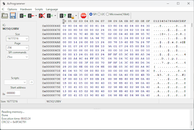
Reading 25xx SPI FLASH with AsProgrammer

Counting time with Arduino (without RTC)

 Posted by:   Posted on:    3 comments

When it comes to counting time using an Arduino or other MCU platform, the use of a RTC (real time clock) circuit is highly recommended. These devices are cheap, have good accuracy and keep counting time even when the main MCU is not powered. They run from a small battery and draw low current. There are quite a lot of Arduino libraries that deal with time and make the interaction with a time source easy. One of these is the Time library by Paul Stoffregen. It is a well written library with internal time based on standard Unix time time_t (number of seconds passed since Jan 1, 1970).

But I wanted something even more basic. I wrote a 50 lines of code function that increments seconds variable each time it is called. When seconds overflow (reach 60), it increments minutes variable and resets seconds. And so on. Only when a time variable changes, it is printed on the output device (16x2 LCD in this case). Around this function I added code that turns the Arduino into a common clock. As a prototype as used the LCD and keypad shield fitted to an Arduino Uno compatible board. The code should compile on any other development board because it doesn't use specific functions or libraries. You will have to adjust LCD pin configuration and keypad buttons (require modification if using buttons connected to digital input pins instead of the analog keypad).

Counting time with Arduino (basic clock)

Truly LCD front panel: the backlight

 Posted by:   Posted on:    No comments
Here is the follow-up of the post where I described how I took out the front panel of a router (yes, a router) and found a way to interface it with Arduino or other development board. It should be noted that the front panel electronics use 3.3V levels, therefore the popular 5V Arduino boards cannot drive the front panel. Using level shifters would complicate things and increase the possibility of something going wrong, so I ended up using a 3.3V STM32 blue pill development board. This is programmed from Arduino IDE, so the code I write is compatible with Arduino development boards.

While I was sampling various pins of the front panel connector with a logic analyzer, I noticed a strange protocol on pin 18. I was able to trace the PCB track from pin 18 near an area that seemed like a DC-DC converter. It directly drove an integrated circuit marked T43. Searching for it revealed some LDO linear voltage regulators, but this was not the case. Pin 18 carried a digital protocol that would be of no use for an ordinary voltage regulator. But without information I could only write code that would mimic the protocol I sampled. Things changed once the GPL source code has been made public. The signal on pin 18 had a meaning. It was necessary to turn on/off and dim the backlight. Upon powering the front panel on the breadboard, the backlight stayed off. You can turn it on by setting pin 18 high but if you want to adjust its level you must send two bytes using a custom serial protocol. Before getting to the code let’s see an overview of the pins and connections on the breadboard.

Front panel connector adapter on breadboard

Router's LCD and keypad interfaced to Arduino

 Posted by:   Posted on:    2 comments
A router with display is not something you see everyday. That’s why when I saw two such routers that were discarded I bought them. At that time I had absolutely no idea if I could install an open source firmware on them (such as OpenWrt). I didn’t even know what type of display do they use. Currently, there is no way of installing a 3rd party firmware on those devices. But the front panel of the router can be interfaced to a microcontroller (only a specific hardware version).

The devices I’m talking about are SerComm SHG1500 routers, used for ADSL internet. They are based on Broadcom BCM6361 SoC and, although this platform is supported by OpenWrt, a specific build for this device or a way to upgrade firmware isn’t known. So I gave up this idea. But upon opening the case, the front panel with LCD display looked like a module that could be used for my projects. The LCD is color TFT, 2.8” size. Next to it there is a capacitive keypad with 5 keys. Front panel plugs into main board using a 2x15 pins, 1.27 mm pitch connector. It seemed good enough to start gathering information.

SerComm SHG1500 front panel with LCD and capacitive keypad

STM32Cube code initialization for “blue pill”

 Posted by:   Posted on:    8 comments
Lately I’ve playing around with the STM32F103 development board known as “blue pill”. Developing software for it is not as easy as for Arduino boards. The MCU contains a 32-bit ARM CPU. I have previously tried to write software for this board using HAL library, but I didn’t get the most out of it because I found the programming model rather complicated.

One of the methods to develop software for this MCU is to use ST HAL library (which uses a higher level API than other libraries for this MCU). I chose the Eclipse IDE with a set of plugins for STM32 family. There is an easier way to get the SDK and IDE with the toolchain called System Workbench for STM32 (recommended by ST too). This is the download directory where you can find all releases for the major operating systems. But before creating a blank project in SW4STM32, you should know that there is a tool which can create this project for you. Not quite blank, as you will configure the MCU with a graphical tool in a step-by-step process.

STM32Cube code initialization for “blue pill”

STM32 “blue pill” easy development with Mbed

 Posted by:   Posted on:    7 comments
The "blue pill" is an STM32F103 based development board. Although it is less popular, the board is cheaper than an Arduino Nano. More than that, STM32F103 is a device with Cortex-M3 ARM CPU that runs at 72 MHz, 20 kB of RAM and 64 or 128 kB of flash memory. The microcontroller (MCU) has USB port, two serial ports, 16 bit PWM pins and 12 bit ADC pins. It runs at 3.3V, but some of its pins are 5V tolerant.

I tried to program this development board using both Arduino IDE and STM32 HAL, but I wasn’t quite satisfied. Arduino framework is simplified and does not take advantage of platform’s features, while HAL was quite difficult for me. Using HAL in Eclipse come with another disadvantage: direct uploading of the binary in flash didn’t work, so I had to use ST-Link tools to upload it, outside of Eclipse. Recently I heard of PlatformIO IDE. This is a development environment supplied as Visual Studio Code or Atom plugin. One of its great advantages is the support for more than 500 development boards! Although VS Code and Atom are cross platform software, they are not at all lightweight, so you’ll need rather good hardware to run them smoothly.

Another great feature of PlatformIO is that for a development board you have multiple framework options. You can program the bluepill using Arduino API, just as you would do in Arduino IDE. Or you can program it using STM32Cube API. But, there is also Mbed OS framework, which I found it to be quite easy to develop.

STM32 “blue pill” easy development with Mbed

How to Count Frequency with Arduino

 Posted by:   Posted on:    5 comments
Counting frequency using an Arduino seemed like an easy task. But most people like to do it the easy, but wrong way: using pulseIn to measure width of a pulse. This limits the maximum frequency that can be measured to about 50 kHz. Besides that, the function samples only a cycle of the signal.

A good way of measuring frequency is by counting input signal transitions that happen in a specific amount of time. This requires knowledge of timers and interrupts. The method is more difficult to implement and to do it right you need to set some registers.

This has been done before and although it was hard to find, I discovered code that can count frequencies up to 8 MHz if the input signal has a duty cycle of 50%. The only drawback is that frequency input pin is fixed to digital pin 5. The upper range is however not limited to only a few MHz. With some extra hardware (a prescaler IC) frequencies of hundreds of MHz can be measured with enough accuracy.
How to Count Frequency with Arduino

Chucks for mini drill tools

 Posted by:   Posted on:    3 comments
Miniature drill tools are a must have for everyone who is making his own printed circuit boards (PCB) at home. Not limited to this, drill tools have many uses as rotary tools. Although the motors you will use for DIY tools have smaller power than a Dremel tool, some of the accessories can be used for small work. You can attach cutting discs, sanding, grinding, carving and polishing attachments. What works and what doesn’t depends on the motor you use, the type of drill chuck and the material you are using it on.

Building your own miniature rotary tool is usually cheaper than buying a Dremel tool. If you want something for PCB drilling only, the motor can be very small. And small motors are found in a lot of devices (do not expect to use a motor from a CD/DVD drive for this purpose, but motors from toys, old cassette players, hair dryers, printers, scanners etc. can drill a hole through a PCB). If you are lucky enough to have a motor from battery operated vacuum cleaner or drill machine (like the 775 motor), you can build something very powerful.

Chucks for mini drill tools

Antenna switch with PIN diodes

 Posted by:   Posted on:    No comments

A PIN diode is a diode with a wide, undoped intrinsic semiconductor region between a p-type semiconductor and an n-type semiconductor region. At high frequencies, the diode behaves as a resistor. The high-frequency resistance is inversely proportional to the DC bias current through the diode. Therefore, if suitably biased, the PIN diode acts as a variable resistor. It has low reverse capacitance, that will attenuate RF signal, unless the diode is forward biased. These properties make it suitable for RF switches.

The device presented here can be used to switch two antennas. It can prove useful in a number of situations. You can have a VHF and a UHF antenna, or you can have two similar antennas that are pointed in opposite directions for different signals. This switch does not require an extra cable and does not cause significant signal losses. A low DC voltage is sent over the coaxial cable to forward bias one diode. If the polarity of this voltage is reversed, then the other diode will be biased.

Lightweight ACARS decoders for RTL-SDR

 Posted by:   Posted on:    No comments
ACARS is a digital data link system for the transmission of messages between aircraft and ground stations. The transmissions usually take place in VHF band, between 130 and 137 MHz. The wide availability of cheap software defined radios makes it easy for anyone to receive and decode ACARS transmissions. Since RTL2832U based USB sticks are the cheapest SDR hardware this is what I will use for reception. There are many tutorials on this subject and most of them involve piping an audio stream from a SDR application to an ACARS decoder application. This is not reliable and takes a lot of resources. More than that, by selecting one frequency, demodulating it and sending the audio stream to ACARS decoder software you are limited to that single frequency.

But there are a few tools that work directly with RTL-SDR hardware, are free, cross-platform and perform ACARS demodulation. More important than that, the software tools you will see here can listen to multiple frequencies at once. The only requirement is that those frequencies should fit in the bandwidth of RTL-SDR (about 2.4 MHz).

Lightweight ACARS decoders for RTL-SDR

Transmission line baluns for VHF and UHF

 Posted by:   Posted on:    1 comment
A balun is a device that converts a balanced signal to an unbalanced signal. Depending on construction, a balun may transform impedance too and may be used for connecting signal lines of different impedances. In radio applications, baluns are used most of the time for adapting a transmission line to the antenna. This post will show you some easy to build baluns, designed for receiving antennas working in VHF and UHF radio and television bands. However, these baluns can be also used for transmitting antennas. They are easy to build because you only use cables similar to the antenna feeder cable.

Most used antenna class for all radio communications is the dipole. Since it's called a dipole, it has two connection points. Therefore it is suited for balanced signals. The antenna can be connected to a receiver using a twin lead cable. But in this case the receiver must have balanced input and similar impedance with the antenna. But the most used type of cable is the coaxial type, which is unbalanced and has a different impedance too. Let's see what are the basic types of connections between the antenna and the feeder cable.

Transmission line baluns for VHF and UHF

Simple Text Menu for ST7920 Graphic LCD

 Posted by:   Posted on:    7 comments
Graphic LCD displays are a good addition for any project where you want to display some data. They look better than the old fashioned 7 segment displays and even alphanumeric LCDs, but more than that, you can use them to build user interfaces and menus. In a previous post, I wrote code for displaying text on a ST7920 128x64 graphic LCD. To save space, I wrote my code from scratch, instead of using a library that draws text in graphic mode and takes up a lot of memory on small microcontrollers. This time, I will continue to add features to the initial Arduino sketch in order to create a simple menu. This menu still uses text mode for displaying items. In this way, you are forced to display a maximum of four items at a time (the display has 4 rows of 16 characters). For highlighting menu items, we'll have to switch to graphics mode and draw rectangles on the screen. I will show you how the graphics RAM of ST7920 is organized and how you can set any pixel you want. The nice thing about ST7920 is that text pixels and graphics pixels are never at the same state. Therefore, if you have written text on a row and afterwards you fill the entire pixels on that row, the text pixels will be cleared ("RGB Controller" is written in text mode, then all pixels from that row are filled - see photo below).

Simple Text Menu for ST7920 Graphic LCD

C Code for Text Mode on ST7920 Graphic LCD

 Posted by:   Posted on:    16 comments
Graphic LCD displays are a good addition for any project where you want to display some data. They look better than the old fashioned 7 segment displays and even alphanumeric LCDs, but more than that, you can use them to build user interfaces and menus. If you interface a graphic LCD with an Arduino or compatible AVR development board, you probably heard about u8g2 library. This is a monochrome graphics display library which supports a lot of LCD controllers and screens of different sizes. It is very easy to use and comes with a lot of functions and display fonts. But this comes with a price. Text is drawn on LCD in graphics mode (this is how it renders different fonts). Combine this with the fact that in serial mode, some LCD controllers are write only. Therefore, the library must keep a part or the entire display data in RAM. This is not a bad thing, but unless you are developing some application where graphics is generated programmatically (something like a game), rather static user interfaces can be written to LCD from a ROM memory and don't need to be kept in RAM all time. And if you're creating a hardware project, you don't usually need to support different LCD controllers, as you'll not replace the LCD.

With this in mind and wanting to learn how to control a graphic LCD, I started to develop my own code. It turned out to be simpler than I thought. Simple code also means simple porting to other platforms. So I started this project with a ST7920 128x64 graphic LCD. I chose ST7920 because it supports serial protocol (SPI) and is 3.3V and 5V compatible. When I bought it I thought I could directly interface it with an OpenWRT router.

C Code for Text Mode on ST7920 Graphic LCD

Ultrasonic Tape Measure with HC-SR04 Sensor

 Posted by:   Posted on:    No comments
The wide availability and low price of microcontrollers makes it possible to update older analog designs to create reliable digital devices that are better and have more features. This time, using an ultrasonic sensor controlled by a microcontroller you can build an electronic distance calculator that can be used as an alternative to a tape measure for distances between 2 and 400 cm. I chose an ATmega development board (Arduino compatible) with an alphanumeric LCD to calculate and display data from the ultrasonic sensor.

The measuring device can be built entirely from ready made breakout boards and it can be powered from a 9V battery. With ATmega as its core, the device can have many features. The software supports current measurement hold and EEPROM storage. Stored measurement can be then displayed at a push of a button. The mode of operation is continuous. Measurements are performed each at 100 ms intervals and displayed on the LCD as long as the device is powered. You can pause the measurement by pressing the button assigned to HOLD function.

The device in the below photo can be built inside a case as long as the sensor's transmitter and receiver are passed through holes in the case. You will also need some holes for the display and buttons.

Ultrasonic Tape Measure with HC-SR04 Sensor

Crossfade Bicolor LED with PS/2 Touchpad

 Posted by:   Posted on:    3 comments
Some while ago, I found a Processing example that would crossfade an Arduino connected bicolor LED depending on mouse position over a window with a gradient. Since I had a touchpad from an old netbook, I decided to use a hardware approach: interface this to Arduino and use it to change LED color by swiping left or right. Horizontal swiping will change the duty factor of PWM signals that light the LED.

This is a simple project that can be built with other kind of input devices like potentiometer or joystick. But, my purpose was to get that touchpad working. I had to use a logic analyzer to determine its pinout. Luckily, since it uses PS/2 protocol, it sends some bytes without connection to a host device. The PS/2 protocol is well documented and pretty easy. ATmega microcontrollers used by Arduino boards don't have hardware support for this protocol, therefore it must be implemented in software. Some searching revealed a lot of libraries for PS/2 devices, but not all worked for me. This may be because the touchpad I used is pretty old and may not support all protocol features.

Crossfade Bicolor LED with PS/2 Touchpad

TSA5523 Tuner Modules from PC TV Cards

 Posted by:   Posted on:    8 comments
Some of the previous posts show methods of generating analog video with microcontrollers and RF modulation of it using ready made modules. Analog video is no longer in use in most parts of the world. TV tuner cards for analog signals are no longer manufactured and old ones are difficult or impossible to install on newer computers because there are no drivers. Despite this, analog video capture devices are cheap and widely available. Most are USB dongles, with video and audio inputs, no tuner.

Since I had some old TV tuner cards that were no longer compatible with my PC or had poor performance, I decided to take the tuners out of them. To my surprise, different tuners from different manufacturers looked pretty much the same on the inside. All of them used the same integrated circuits. The tuners I found are actually complete receivers, with included demodulator. This means you can get analog audio and video straight from the module pins. There are also modules with FM support, with stereo decoder.

In the photo below, you can see two tuners. The top one has FM radio support. You can see that it's similar to the other, but the rightmost compartment has some additional filters for FM IF.

Tuners from TV cards

USB Power Supply for Breadboard

 Posted by:   Posted on:    No comments
Breadboards are very useful for quickly building electronic circuits. But these circuits require power. The popular breadboard power supply you will find on the market is powered from more than 8 V by an AC-DC adapter. They can provide both 5V and 3.3V from linear 1117 regulators. These regulators can supply a maximum of 800mA, but because they work in linear mode and the PCB is not well built for heat dissipation, the current you can draw from such a device is very limited.

While trying to interface a gas sensor and a TV card tuner to an Arduino, I found that I had troubles powering them. Each of the mentioned devices need about 200mA. Both Arduino and the breadboard power supply use linear voltage regulators to provide 5V. I tried to use the breadboard power supply, but the regulator became hot immediately. Being fed with 12V, the 1117 regulator needed to dissipate (12 - 5) x 0.2 = 1.4 W. That's a lot for its small package.

I needed a better power supply. And I want it for breadboard projects. USB seems to be a pretty good power source, being able to provide at least 500mA. So I designed my own power supply. Since is USB powered, I thought it would be a good idea to have an USB port where I could plug development boards, without needing another computer USB port.

USB Power Supply for Breadboard

Program Arduino Pro Mini with CH341A dongle

 Posted by:   Posted on:    3 comments
Arduino Pro Mini is a development board based on ATmega168 or ATmega328 microcontroller. Unlike other members of the Arduino family, this board does not have an USB port for PC connection. To program it, you need an USB to serial TTL converter. There are many choices here, and the Arduino Pro Mini has a pinheader port that matches the pinout of FTDI USB serial breakout boards. ATmega MCU doesn't need all serial port pins. It requires serial data pins RxD and TxD and also DTR, which is connected to reset pin.

CH340 is another USB serial interface. It can be found at the core of the cheapest USB serial adapters, but these dongles are difficult to connect to Arduino because there is no power pin and no exposed DTR pin. The power pins on the CH340 USB breakout board are used with jumpers to select voltage levels (3.3V or 5V).

CH341A is a complex interface chip which adds parallel, I2C or SPI interface. It is used by memory programmers. However, by setting a jumper, it works as an usual USB to serial adapter. I will be using here a popular device based on CH341A, the black MiniProgrammer, to program an Arduino Pro Mini compatible board.
Program Arduino Pro Mini with CH341A dongle

Measure RPM with Slotted Optical Switch

 Posted by:   Posted on:    No comments
Building an RPM counter is very easy with an optical switch and a way of counting pulses generated by the switch. A microcontroller, a frequency meter and even a logic analyzer can be used for this. Here, I will be using the cheapest and popular method: an Arduino. Optical switches are devices made of an emitter LED, usually infrared type and a receiver diode. Between the IR emitting LED and the receiver there is a slot. An opaque piece can pass through this slot and block IR beam. This will be detected by the receiver diode and its output will change state.

The piece that will block IR light will be a flange with a slot (a cutout area from the disc). When this passes through the switch's slot, the light reaches the receiver diode. Therefore, rotations are translated into a digital signal with a constant duty factor, dependant on flange configuration. The frequency of this signal needs to be measured and converted into RPM.

775 motor fitted with optical switch

I2C Analog TV Modulator controlled by Arduino

 Posted by:   Posted on:    33 comments
Analog video is getting replaced by digital signals which provide better resolution and picture without noise or interference. But, analog video signal is easy to generate with simple hardware and then it can be FM modulated for broadcasting over a wire. I2C controlled RF modulators are common modules in obsolete VCRs and set top boxes. Most of them cover the entire UHF band and support multistandard sound carrier frequencies. Once taken out of its device, the modulator needs a microcontroller to set up its frequency and other parameters.

Using an Arduino board with LCD and keypad shield a full featured modulator can be built. Arduino can be used to generate video too, but a single board can't use I2C and generate video in the same sketch. You'll need different boards if that's what you want to do.

I used for this project a Samsung RMUP74055AD modulator with MBS74T1AEF controller. Some searching reveals the same IC is also used by Tena TNF0170U722 modulator. Some datasheets will come up too, if you search for them. Anyway, these modulators are 5V devices.

RMUP74055AD UHF RF modulator

Arduino Thermometer with... TV Output

 Posted by:   Posted on:    9 comments

Analog video is getting replaced by digital signals which provide better resolution and picture without noise or interference. Although receivers for digital signals are cheap and popular, devices for generating such signals are expensive and intended for professional use only. On the other hand, analog video is easy to generate with simple hardware. You can even broadcast it over RF (on wire, not on air) with common modulators (standalone devices or modules from video game consoles, set top boxes, VCRs etc.).

An easy way to generate video signal is by using a microcontroller and some resistors. I'll use for this purpose an Arduino board (ATmega 328p) with the TVout library. The video signal is of low resolution and black&white. But it can be used to display data on a TV screen. If you no longer own a TV with analog video input, an USB capture card can be used. TVout library is interrupt based, therefore will interfere with some of other interrupt dependent microcontroller features.

Arduino Thermometer with... TV Output

Compute Heat Index with Arduino and DHT Sensor

 Posted by:   Posted on:    2 comments

The heat index is a parameter that takes into account temperature and relative humidity, to determine the apparent temperature or the human perceived equivalent temperature. Heat index was developed in 1978 by George Winterling and was adopted next year. It is also known as humiture, according to Wikipedia contributors.

To compute this index, you need to know current temperature and relative humidity. An easy way to find both is by using an Arduino development board with a DHT sensor (DHT11, DHT22). These sensors measure temperature and humidity and send it to the microcontroller using a digital protocol. Thus, there is no need for calibration. You can read the values directly from the sensor module. However, you should take into account that the accuracy of these sensors is not the best. DHT11 has an accuracy of +/-5% for humidity and +/-2 degrees Celsius for temperature. DHT22 (AM2302) is slightly better with an accuracy of +/-2% for humidity and +/-0.5 degrees Celsius for temperature. More than that, DHT22 has extended ranges for both temperature and humidity.

Compute Heat Index with Arduino and DHT Sensor

Audio Amplifier with Common Transistors

 Posted by:   Posted on:    1 comment

Here is the schematic of a small audio amplifier that will provide up to 300mW to an 8 ohm load and can be used in low power devices like battery powered radios. This circuit is an alternative to the LM386 IC. Due to the simplicity of the schematic, the circuit can be built also on breadboard, for those of you who want to experiment and learn how an amplifier works.

The design is straightforward. A common small signal NPN transistor (like BC547, 2N2222, 2N3904, S8050) drives a balanced power amplifier made of similar transistors. The output transistor pairs can be BC327 with BC337 or S8050 with S8550. They must handle peak currents of 300-400mA (this is why BC547/BC557 or 2N3904/2N3906 should not be used here). The amplifier can be powered from a 9V battery or from a 12V power source. The circuit draws a current of about 170mA. Quiescent current is less than 10mA.

Audio amplifier with common transistors build on breadboard
Audio amplifier build on breadboard